4 Port Directional Coupler
Types of 4 port directional coupler
AWG Tech has more than 1000 different models of 4 port directional couplers. The directional couplers can be broadly classified into the following categories:
Aside from 4 port directional coupler, the list below gives you a list of other common directional couplers.

4 Port Directional Coupler: A Short Rundown
RF directional couplers are sometimes being utilized in RF design applications. They are RF passive components that’s utilized to pair together a particular power proportion that’s travelling in a single transmission line and exits to another port or connection. There are a lot of applications of directional couplers in any RF design, ranging from through line power sensors or in transmitter automatic level controls.
As they are pragmatically useful, a 4 port directional coupler allows power levels to be sensed without making a direct link to the transmission line carrying the power. In addition, directional couplers can be applied with the utilization of different techniques and these include stripline, coaxial feeder and lumped or discrete elements.
The Directional Coupler Basics
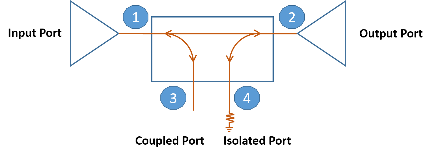
As mentioned above, there are four ports in a single directional coupler component. They are typically termed as the following:
- The Input Port (Incident and the first port)
- The Transmitted Port (Output and the second port)
- The Coupled Port (Forward Coupled and the third port)
- The Isolated Port (Reverse Coupled and the last port in the component)
Generally speaking, the main line is the one that lies in between ports 1 and 2. Basically, this may be more compatible to carry high power levels and it may possess a larger set of RF connectors, if it’s a component that comes with RF connectors.
The other ports are basically the ones who are more suited to carry low powers as they are only intended to hold a small fraction of the main line power. Ports 3 and 4 may even have smaller connectors to determine them from the main line ports of the directional coupler.
The Directional Coupler Specifications
Just like any other RF and microwave components, there are quite a few specifications that’s associated with directional couplers. Some of the important specifications for directional couplers are the following:
- The Coupling Loss: This is the amount of power that’s lost to the coupled port and to the isolated port. Assuming a valid directivity, the power being ported over unintentionally to the isolated port will be negligible compared to power ported over intentionally to the coupled port.
- The Main Loss: This refers to the resistive loss due to heating (away from the coupling loss). This value is added to the theoretical power reduction that is ported to both the coupled and isolated ports (referred to as coupling loss).
- The Directivity: This pertains to the difference in the levels of power between ports 3 and 4 (in line with isolation). This is an estimate of how independent both the aforementioned ports are. Plus, due to it being impossible to establish the ideal coupler, there will always be some amount of unintended pairing between every signal paths.
- The Isolation: This is the difference in power levels between ports 1 and 4 (related to directivity).
A single 4 port directional coupler has the following basics and specifications. Fully comprehending these points will help one establish a firm understanding on how they work on any RF design.