Directional Coupler Supplier Spain – AWG Tech
AWG Tech supplies directional couplers to many countries worldwide. In Spain, our directional couplers are widely used in C-Band transceivers to sample and monitor the output power of power amplifiers.
AWG-DC-4G4-5G0-20-SF -1 is a C-Band directional coupler and has an operating frequency from 4.4 GHz to 5 GHz. AWG-DC-4G4-5G0-20-SF -1 is a low loss 20 dB coupler. The insertion loss in the main line is 0,4dB max and it is capable of handling up to 50W of power.
AWG Tech also supplies wideband directional couplers, which have operating frequencies spanning multiple octaves. We have wide band directional couplers that operate from 6 GHz to 18 GHz. Our ultra-wideband directional couplers can be used from 1 GHz to 18GHz.
Check up our lineup of directional coupler.
Directional Couplers Categorized by frequency bands
- 5 – 1000 MHz directional coupler
- L-band directional coupler (1-2 GHz)
- S-band directional coupler (2-4 GHz)
- C-band directional coupler (4-8 GHz)
- X-band directional coupler (8-12 GHz)
- Ku-band directional coupler(12-18GHz)
- Wideband directional coupler
Directional Couplers Categorized by Type
- Bi-directional coupler
- Hybrid coupler
- Dual directional coupler
Directional Couplers Categorized by coupling
- 10 dB directional coupler
- 20 dB directional coupler
- 30 dB directional coupler
Enquire about our directional coupler
Fill in the enquiry form below to find out more about our directional coupler. Let us know the required operating frequency of the directional coupler and the coupling factor for the coupler and we will get back to you in 3 business days.
Did not find out you need in our catalogue?
No worries. We make customized directional couplers as well. Simply send us an enquiry today!
The Important Basics behind Directional Couplers
RF Directional Couplers, classified as RF passive devices, are sometimes utilized in other RF design applications. They’re used to partner with a certain magnitude of power circulating through one transmission line out through another port. Because of this, applications are many in RF manufacturing.
Such applications range from line power sensors to transmitter automatic level control. According to any directional coupler supplier Spain, they’re pragmatically useful. This is because they allow power levels to be detected without establishing direct connection to the transmission line bringing the power.
RF directional couplers can be carried out by utilizing different methodologies including strip line, coaxial feeder and lumped or some secret factors. Suppliers may place them inside different packages from blocks with RF connectors, or solder pins.
Also, they may be placed on a substrate carrier or manufactured as a piece for a larger unit having other functions.
Directional Couplers Definition: The Operational Description
Directional couplers function as a four-part network, although one of the ports may be internally terminated with a load. Directionality is usually reliant on internal symmetries and partnerships.
In a four-port configuration, one of the ports is secluded at another port; energy is then partnered from the referenced port. The energy balance, after losses in coupling, leaves the remaining port referred to as the “mainline”.
As the name implies, a directional coupler tests the energy based on the energy flow’s direction.
Directional Couplers: The Basics
As mentioned above, a directional coupler is a four-port device. The four of them are generally termed:
- Input (Incident, Port 1)
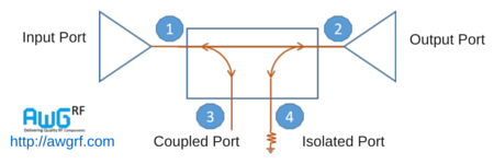
- Transmitted (Output, Port 2)
- Coupled (Forward Coupled Port, Port 3)
- Isolated (Reverse Coupled Port, Port 4)
Take note that the terms in parentheses refer to the alternative names given for each port.
Basically, the main line is the one in between ports 1 and 2. This may be more suited to carry high power levels and may have bigger RF connectors, if it’s a unit that comes with RF connectors.
Meanwhile the other ports are suited for lower powers as their main purpose permits them to carry only a small portion of the main power.
Ports 3 and 4 could have smaller connectors to differentiate them from the main port lines of the coupler. Regarding the above stated that one of the ports may be internally discharged, this is due to a matched load which would usually amount to 50 ohms.
Although the ports are labeled on the device, this is more of a physical constraint as there are ports that’ll be made to hold greater power than the rest. As a matter of fact, any port can be the input.
This will result in the directly connected port to be the transmitted port, the neighboring port being the coupled port, and the diagonal port transforming into the isolated port.
Click here to add your own text
The basics presented above for directional couplers can help clients understand what their functionality is. Without comprehending what they are first, clients may have a hard time deciphering what they are used for.
Directional coupler supplier Spain companies are making millions of them for clients who are planning to improve their RF and microwave communication systems, thus knowledge of the basics is imperative.